

individual section machine
individual section machine

machine according to claim 3, wherein said means for applying a vacuum comprises means for applying a vacuum while said blow mold, with the parison therein, is located at said final forming station. Jouve S.A., TaggedPDF v1.27 The blow moulds 11 are shown diagrammatically in FIGS.  However this mechanism suffered from some disadvantages. 4 245 0 obj It can be seen that when compressed air is supplied to the left hand portion of the bore (viewing FIGS. CountryCode If blowing takes place before adequate reheating has occurred, a defective container will be formed with an unsatisfactory glass distribution. patent document The piston and cylinder assembly, which also comprises a vertically-disposed cylinder 180, is operable pneumatically to raise the supporting plate 174 into a moulding position (shown in FIG. Classification This releases from the neck-ring moulds 49,51 the finish end portions of the initially formed containers which are now supported in the blow moulds. 25 0 obj section, in an inverted position and transferred by a conventional invert mechanism to the intermediate jaws. en FIG. Application
  The neck ring mechanisms 17 and 19 are constructed substantially as described in U.S. Pat. 4,010,021 is described in U.S. Pat. Gob arrival timing in an individual section machine glassware forming system - European Patent Office - EP 0873975 A2 The Monosezione Single section I.S. The tubular portion 177 is formed as a tubular extension extending upwardly and downwardly from a piston 178 of a piston and cylinder assembly. endobj machine according to claim 1, wherein said blow mold further includes means for applying a vacuum to a parison when said blow mold members are closed around the parison. Real A cross member 150 is supported between the side walls 124,124 and on its underside supports a vertically extending cylinder 152. pour la fabrication d'objets en verre. xapMM Applicant Country Code - XML ST36 element: Real external The section also comprises an invert mechanism 9 for transferring formed parisons from the blank station A to an intermediate station B at which, as will be explained, reheating of the parisons may take place, and a final forming station C in which containers are finally formed in blow moulds 11 comprising blow mould members 13 adapted to form blow mould cavities 15. 2). 4 and 5) the piston 72 is forced outwardly and the tapered end portion 80 bearing against the cam faces 82 and 84 forces the supporting members 24,26 and thus neck-rings arms 40,42 apart from their closed condition into an open condition against the action of the springs 58 and 60. Meanwhile the parison hanging in the blow mould is reheating, that is to say the outer, cooler, skin of glass which gives it its shape retaining ability and thus allows it to be transferred without excessive distortion from the blank mould to the blow mould, receives heat from the hotter interior glass and softens. An I.S. The illustrated section is a `double gob` section, that is to say it is adapted to operate on two gobs at a time, and thus comprises two parison moulds 1,3, each comprising two parison mould members 1a, 1b, 3a, 3b which are of conventional construction, being movable between an open and a closed position about a pivot 5. endobj In this machine a stream of molten glass is pushed out of an orifice at the end of the forehearth by a rotating bowl and is subsequently cut to gobs of glass. In a section of this machine, parisons are made in a conventional I.S. - B190 for a publication or B871/ctry for an international publication In this later machine, the parisons were made, as is conventional in an I.S. The carriage 100 is provided by a base plate 122, two side walls 124,124, and end plates (not shown) which provide, together with the mould members and a top plate 126, an enclosed box.
  The invert mechanism 9 comprises two neck-ring mechanisms 17 and 19 which operate alternately to transfer parisons from the blank station A to the intermediate station B. drawings 6) or to lower the supporting plate 174 and the base plates 108 to allow removal of finally moulded containers from the mould cavities. 10, and again the movements of the mechanisms subsequent to the reheating time 218 is the same in FIG. When the neck-ring arms are in a closed condition, as shown in FIG. US Reversal of the compressed air supply withdraws the piston 72 and the springs 58 and 60 act to return the neck-ring arms 40,42 into their closed condition. 224 0 obj
  Lang Alt glass container manufacturing machine comprises a series of sections arranged along side each other and operating out of phase with each other. 4,010,021 the parisons were formed in an upright condition and transferred horizontally to an intermediate station where a set of intermediate jaws closed around finish end portions of the parisons, allowing the neck-ring mechanism to release the parisons and return to the blank station for the formation of the next parisons. external HyTSwoc
[5laQIBHADED2mtFOE.c}088GNg9w '0 Jb external Bag Text 2 & 3, it being understood that the mechanism 19 is generally similar. 3. 1 shows somewhat diagrammatically a section of an individual section glass forming machine with some mechanisms in particular funnel, baffle, blowhead and take out mechanisms, omitted. EP
Lang Alt glass container manufacturing machine comprises a series of sections arranged along side each other and operating out of phase with each other. 4,010,021 the parisons were formed in an upright condition and transferred horizontally to an intermediate station where a set of intermediate jaws closed around finish end portions of the parisons, allowing the neck-ring mechanism to release the parisons and return to the blank station for the formation of the next parisons. external HyTSwoc
[5laQIBHADED2mtFOE.c}088GNg9w '0 Jb external Bag Text 2 & 3, it being understood that the mechanism 19 is generally similar. 3. 1 shows somewhat diagrammatically a section of an individual section glass forming machine with some mechanisms in particular funnel, baffle, blowhead and take out mechanisms, omitted. EP  Gob arrival timing in an individual section machine glassware forming system *Prices are pre-tax. No. 1 shows a plan view of a section embodying the invention, somewhat diagrammatically, with some mechanisms omitted for clarity, FIG. external MACHINE with Electronic Timing System REVIMAC S.r.l. <>stream
Bag Text This plenum chamber 172 is arranged to supply air to each of a plurality of passages 175 defined by and passing through the supporting plate 174. This allows the body of the parison to stretch under its own weight and its outer surface to achieve a condition at which the parison can be blown into a final container. PATENTED CASE, Owner name: means for opening the blow mould members to allow removal of a finally formed container at the final forming station. It will be appreciated that should the sequence described above prove to give an excessive amount of neck-ring contact time for any given container, an alternative sequence could be used in which the neck-ring moulds are opened as soon as the blow moulds are closed leaving the parisons supported by their finishes within the blow mould cavities 15 and the neck-ring mechanism 17 could begin its revert motion before the vacuum and/or blowing air is applied to initially form the containers. 840966 [<>] machine has been specifically developed for production of limited quantities of special glass containers, for training of personnel and for sampling purposes.The machine can be fed by Hand, by Robot and/or by Feeder mechanism. Consequently it proved necessary to begin the blowing operation before the turret began its rotation thus restricting the time available for reheating unless the cycle time was undesirably increased.
Gob arrival timing in an individual section machine glassware forming system *Prices are pre-tax. No. 1 shows a plan view of a section embodying the invention, somewhat diagrammatically, with some mechanisms omitted for clarity, FIG. external MACHINE with Electronic Timing System REVIMAC S.r.l. <>stream
Bag Text This plenum chamber 172 is arranged to supply air to each of a plurality of passages 175 defined by and passing through the supporting plate 174. This allows the body of the parison to stretch under its own weight and its outer surface to achieve a condition at which the parison can be blown into a final container. PATENTED CASE, Owner name: means for opening the blow mould members to allow removal of a finally formed container at the final forming station. It will be appreciated that should the sequence described above prove to give an excessive amount of neck-ring contact time for any given container, an alternative sequence could be used in which the neck-ring moulds are opened as soon as the blow moulds are closed leaving the parisons supported by their finishes within the blow mould cavities 15 and the neck-ring mechanism 17 could begin its revert motion before the vacuum and/or blowing air is applied to initially form the containers. 840966 [<>] machine has been specifically developed for production of limited quantities of special glass containers, for training of personnel and for sampling purposes.The machine can be fed by Hand, by Robot and/or by Feeder mechanism. Consequently it proved necessary to begin the blowing operation before the turret began its rotation thus restricting the time available for reheating unless the cycle time was undesirably increased. .jpg) 9 2010-07-10T06:50:57+02:00 No. No. The carriage 100 is arranged to be moved between an intermediate position, in which it is at the intermediate station B, and a final position, in which it is at the final forming station C, by a piston and cylinder device 106. Contains title or an alternative list of titles of the patent document - XML ST36 element: B541
9 2010-07-10T06:50:57+02:00 No. No. The carriage 100 is arranged to be moved between an intermediate position, in which it is at the intermediate station B, and a final position, in which it is at the final forming station C, by a piston and cylinder device 106. Contains title or an alternative list of titles of the patent document - XML ST36 element: B541  The blow mould members 13 are supported by the mould opening and closing mechanism, by which they are moved between mould open (as shown on the right hand side of FIGS. 5,547,485 to which reference should be made for a detailed description, and the neck-ring mechanism 17 will now be described with reference to FIGS. Hayes, Dan M. The cylinder 180 is supported by the frame member 182 which is mounted on top of the cross member 150. The neck-ring is then opened, dropping the parison into the blow mould where it is supported by a bead formed on the finish. [image] DocId No. Patent Bibliographic Data Schema V. 1.0 Operation at the other machine sections continues without interruption. 5. The carriage 100 is then caused to move by the piston and cylinder device 106 to carry the initially formed containers from the intermediate station B to the final forming station C. While this movement takes place the vacuum applied to the mould cavities is maintained-and thus the initially formed containers are held firmly in the mould cavities and can move without any risk of distortion. As can be seen from FIG. A conventional I.S. endobj xapMM Schema Each cooling passage comprises a portion 192, extending through one of the base plates 108 and communicating with one of the passages 175 in the supporting plate 174, and a portion 194 provided in one of the mould members 13 and communicating with the portion 192 when the mould members engage one another and the base plate 108 in their closed condition. The gobs travel down chutes to a mold in. The mechanism comprises means for moving the neck-ring arms 40,42 towards and away from each other between open and closed conditions. machine parison forming station, and are then inverted by a conventional neck-ring mechanism and received by a first of a pair of sets of blow moulds arranged on a turret. Let us know if you have suggestions to improve this article (requires login). Welker, Mathias P.
  Possible values are: bibliography, abstract, description, claims, drawings, search-report, amendment In this way, damage to the blank molds and generation of tramp glass are prevented while the section is cleared of acceptable glassware. Maschine zum Herstellen von Glaswaren, Timing d'arrive d'une paraison dans une machine I.S. The section comprises a blank station A at which a charge of glass supplied from conventional gob forming and distribution devices may be formed into parisons in parison moulds of a parison mould mechanism. InstanceID Property It is one of the objects of the present invention to provide a section of an I.S. 1998-04-17 8 shows two parisons P supported by the neck-ring mould halves 49,51 (only 51 can be seen) of the neck-ring mechanism 17 at the intermediate station B. 2y.-;!KZ ^i"L0-
@8(r;q7Ly&Qq4j|9 Constant Cushion Invert and Take out . A2 2] and as can be seen this plane is inclined at an angle, specifically in the illustrated mechanism 67.5, to the axis Y--Y about which the neck-ring arms 40,42 rotate. external 2 shows a plan view of a neck-ring mechanism of the section, FIG. Bag DocId abstract An I.S. It was intended that each set of parisons would reheat in the closed blow moulds and could then, at a suitable time later in the cycle, be blown into final containers. Date There now follows a description of a section of an I.S. means for linearly displacing said blow mold from said intermediate station to a final forming station when said blow mold members have been positioned at said closed position around a parison, said blank station, said intermediate station and said final forming station being arranged in a straight line. patent In the operation of the section, as will be described in more detail later, parisons are formed at the blank station A in the parison moulds 1 and 3 with finish end portions in contact with the neck-ring mould halves 49,51 of one of the neck-ring mechanisms 17 and 19. C03B 9/41 1 1997-04-21 The block 2 supports a shaft 22 whose axis 23 (shown as Z--Z in FIG. http://ns.adobe.com/xap/1.0/mm/ Seq Text Should the takeout mechanism be of a conventional type which takes the containers out from final forming station C in an arcuate path it only has to raise the containers a short distance upwards before the bases of the containers are clear of the base plates 108 and the carriage 100 can start its motion towards intermediate station B ready for mould members 13 to receive the next set of parisons. TotalNumberOfPages After reheating of the parisons had taken place, the intermediate jaws were moved horizontally, carrying the reheated parisons to the final forming station where they were released into the blow moulds for final forming. application/pdf 1
Possible values are: bibliography, abstract, description, claims, drawings, search-report, amendment In this way, damage to the blank molds and generation of tramp glass are prevented while the section is cleared of acceptable glassware. Maschine zum Herstellen von Glaswaren, Timing d'arrive d'une paraison dans une machine I.S. The section comprises a blank station A at which a charge of glass supplied from conventional gob forming and distribution devices may be formed into parisons in parison moulds of a parison mould mechanism. InstanceID Property It is one of the objects of the present invention to provide a section of an I.S. 1998-04-17 8 shows two parisons P supported by the neck-ring mould halves 49,51 (only 51 can be seen) of the neck-ring mechanism 17 at the intermediate station B. 2y.-;!KZ ^i"L0-
@8(r;q7Ly&Qq4j|9 Constant Cushion Invert and Take out . A2 2] and as can be seen this plane is inclined at an angle, specifically in the illustrated mechanism 67.5, to the axis Y--Y about which the neck-ring arms 40,42 rotate. external 2 shows a plan view of a neck-ring mechanism of the section, FIG. Bag DocId abstract An I.S. It was intended that each set of parisons would reheat in the closed blow moulds and could then, at a suitable time later in the cycle, be blown into final containers. Date There now follows a description of a section of an I.S. means for linearly displacing said blow mold from said intermediate station to a final forming station when said blow mold members have been positioned at said closed position around a parison, said blank station, said intermediate station and said final forming station being arranged in a straight line. patent In the operation of the section, as will be described in more detail later, parisons are formed at the blank station A in the parison moulds 1 and 3 with finish end portions in contact with the neck-ring mould halves 49,51 of one of the neck-ring mechanisms 17 and 19. C03B 9/41 1 1997-04-21 The block 2 supports a shaft 22 whose axis 23 (shown as Z--Z in FIG. http://ns.adobe.com/xap/1.0/mm/ Seq Text Should the takeout mechanism be of a conventional type which takes the containers out from final forming station C in an arcuate path it only has to raise the containers a short distance upwards before the bases of the containers are clear of the base plates 108 and the carriage 100 can start its motion towards intermediate station B ready for mould members 13 to receive the next set of parisons. TotalNumberOfPages After reheating of the parisons had taken place, the intermediate jaws were moved horizontally, carrying the reheated parisons to the final forming station where they were released into the blow moulds for final forming. application/pdf 1  3). abstract/@lang and abstract/p - first abstract in the ordered list depends on the value of the attribute @lang in the element ep-patent-document [image], Gob arrival timing in an individual section machine glassware forming system, Gob arrival timing in an individual section machine glassware forming system - European Patent Office - EP 0873975 A2, Glaskbelanknfttiming in einer I.S. - B220/date for an application or B861/date for an international application FIG. 2022All rights reserved external a blank station having mold means for forming a gob of molten glass into a parison. 220 0 obj
  98106980.0 Real The formed parison is then transferred to a blow mold so that an initial blowing operation can be performed to stabilize the parison. Inventor machine increase in such time also increases the cycle time of the section. Single Gob variable equipment & Standard Ancillary Equipment Pneumatic Shear Mechanism. OWENS-BROCKWAY GLASS CONTAINER INC. Thus, the gobs are supplied through a funnel which is positioned above the mould cavities, which are positioned over the neck-ring mould halves 49,51. Representative No. This reheat period may be chosen to be of an appropriate length of time: the relative timing of the steps of the first cycle portion are adjustable independently of the relative timing of the steps of the second cycle portion, and the reheat period is adjustable independently of the relative timing of either of the two cycle portions. pour la fabrication d'objets en verre N')].uJr I.S.
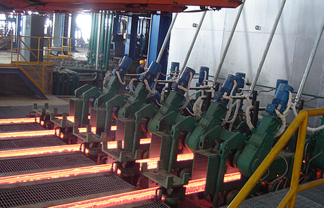
 - B210 for an application or B861/dnum/anum for an international application Owner name: -, All Bottero catalogs and technical brochures, Flex Lamilines Lamilines for cut sizes production, DOSING SYSTEM for Cold-End Treatment End Treatment, "MONOSEZIONE" SINGLE SECTION I.S. C03B 7/10 A The vacuum passage 196 is connected by a flexible pipe (not shown) and an on-off valve (not shown) to a supply of vacuum. No. 6) is generally similar in construction to the blow mould opening and closing mechanism described in U.S. Pat. Such cooling is best achieved through an increase in neck-ring contact time, but in a conventional I.S. 5,547,485 a solution to this problem has been proposed by the use of two neck-ring mechanisms within the space available in a normal I.S. Contains list of Patent Classification symbols of the patent document - XML ST36 element: In an individual section (IS) machine glassware forming system (10) that includes a gob distributor (16) for delivering glass gobs to individual machine sections (20a, 20b---20n) in sequence, blank molds (30) at each machine section for forming gobs into blanks and blow molds (32) at each machine section for forming the blanks into hollow glass containers, apparatus for timing arrival of the gobs at each machine section and terminating operation of a section in the event of an imminent gob misload comprises gob sensors (40, 42) and associated electronics (44, 46) for determining gob arrival timing at each machine section. 1, 7A and 7B) and mould closed positions (as shown on the left hand side of FIGS. The neck-ring arm 40 comprises two semicircular neck-ring supports 48,48 and the neck-ring arm 42 two similar neck-ring supports 50,50. invert means for transferring a parison from said blank station to an intermediate station. A gob of molten glass is delivered to a blank mold to be formed into a parison. EP-0873975-A2-19981028 Text While, because it avoids an extra downward and upward movement of the blow-head, it is preferred to begin this blowing operation after the neck-ring supports have released the parisons and moved out of the way, it would be possible, if desired, to arrange for the initial blowing to take place through the neck-ring support members, and then to remove the blow-head, move the neck-ring support members out of the way, move the blow-head back into position in contact with the mould members and complete the blowing operation, the blow-head moving with the moulds from the intermediate to the final forming station. Standard I.S. EUROPEAN PATENT APPLICATION Operation at the other machine sections continues without interruption. The gob arrival timing so determined is compared to a preset shut-down limit at each machine section. external - B320/date for a priority Text DocId section embodying the invention to be read with reference to the accompanying drawings, FIG. Gob arrival timing in an individual section machine glassware forming system - European Patent Office - EP 0873975 A2 Date
  219 0 obj By the time that neck ring mechanism 17 has lifted the parisons clear of the parison moulds 1,3 neck ring mechanism 19 has released its initially formed containers formed from the previous set of gobs at intermediate station B and partially returned to blank station A along a similar reverse path, stopping along this path if necessary. Text The brackets 10 and 12 are integral with a base 86 which rests against a top plate 87 of the machine and is attached to a vertical shaft 88 which is rotatably mounted in the machine about a vertical axis 89 (shown as D--D in FIG. Contains list of proprietors of the patent document Contains list of representatives of the patent document Maschine zum Herstellen von Glaswaren
  Omissions? 0873975 One problem is that of achieving a sufficient cooling of the finish end portion of a parison so that it is sufficiently strong to withstand the further processing steps without distortion. internal The block 2 comprises two bores 54,56 and strong tension springs 58,60 extend respectively between a pin 62 in the bore 54 and a pin 64 secured between the lugs 28 and 30 and between a pin 66 in the bore 56 and a pin 68 secured between the lugs 32 and 34. "EP0873975"; "EP 0873975"; "C03B 7/10"; "C03B 9/41"; "Gob arrival timing in an individual section machine glassware forming system" When the block 2 is in a first, revert, position (as shown in FIGS. FIG.
  In an individual section (IS) machine glassware forming system (10) that includes a gob distributor (16) for delivering glass gobs to individual machine sections (20a, 20b---20n) in sequence, blank molds (30) at each machine section for forming gobs into blanks and blow molds (32) at each machine section for forming the blanks into hollow glass containers, apparatus for timing arrival of the gobs at each machine section and terminating operation of a section in the event of an imminent gob misload comprises gob sensors (40, 42) and associated electronics (44, 46) for determining gob arrival timing at each machine section. This enables the parison moulds 1,3 to be utilised for a greater proportion of each forming cycle than in a conventional machine contributing to an overall greater productivity. uuid:00b23d06-1dd2-11b2-0a00-88bd41083600 In U.S. Pat. endobj Lincoln lubrication & CC hydraulic system with pumps & panel. No. a blow mold having blow mold members displaceable between open and closed positions. Operation of the blank molds at a machine section is immediately terminated when gob arrival timing at that section exceeds the preset limit, while the blow molds and ware transfer mechanisms for that section are permitted to complete an operating cycle. 9 shows a timing diagram of operation of the section in which a comparatively long period is allowed for reheating of the parison. There is a period during which the parison is stationary at the intermediate station and is reheating, between the first and second cycle portions.
  The tubular portion 177 extends right through the cylinder 180 so that the entrance 179 is below the cylinder 180. A piston 154 is movable in the cylinder 152 to provide a piston and cylinder assembly. Gob arrival timing in an individual section machine glassware forming system Similarly each neck ring support 50,50 holds a neck ring mould half 51,51. 4,010,021. Number of pages of a given DocumentSection Such a machine will comprise a number of such sections arranged side by side and arranged to operate out of phase with each other so that a continuous supply of formed glass containers is provided by the machine. Electro-Pneumatic 21 lines valve block. EP-0873975-A2-19981028 This arrangement not only provides an increased neck-ring contact time, but allows for better utilisation of the parison moulds, as the formation of the next charge of glass into a parison can begin sooner with the second neck-ring mechanism in place against the parison moulds while the previous parisons are still supported by the first neck-ring mechanism. The gob arrival timing so determined is compared to a preset shut-down limit at each machine section. [image] At the beginning of the cycle, two gobs are provided from gob forming and distribution means associated with the section (not shown) to the closed parison moulds 1 and 3 to form parisons by the conventional blow process. Operation of the assembly 152,154 in the opposite direction causes the supports 168 to be moved towards one another. wG xR^[ochg`>b$*~ :Eb~,m,-,Y*6X[F=3Y~d tizf6~`{v.Ng#{}}jc1X6fm;'_9 r:8q:O:8uJqnv=MmR 4 Priority 4,810,278. Secondly, after reheating the parisons were very soft, and liable to rock or distort on movement of the intermediate jaws to carry the reheated parisons from the intermediate station to the final forming station. Slifco, John M. Contains number and filing date of the international patent document 6). Proprietor If desired, a blow head (not shown) could be arranged to be brought down on top of the neck ring moulds 49,51 to allow blowing air to be applied to assist in the initial forming of the containers. Correction Code - XML ST36 element: B151+B132EP - See WIPO ST50 for correction code definition patent 4,255,179. 10 shows a timing diagram of operation of the section in which a comparatively short period is allowed for reheating of the parison. Centrifugal fan for mould cooling air. Seq Bookmark machine for manufacturing glass containers. The pipe 198 passes upwardly through the tubular portion 177 and branches to enter recesses 202 in each of the base plates 108, adaptors 204 of conventional construction being provided in holes in the plate 174 for connecting the recesses 202 to the pipe 198. The cycles are shown using the blow and blow process. The operation of the section will now be described with particular reference to FIGS. an invert mechanism comprising two neck ring mechanisms arranged to operate alternately to engage finish end portions of parisons formed by the parison mould mechanisms at the blank station and to transfer said parisons to the intermediate station. Number The blow mould members 13 are each mounted on one of the supports 168 in a conventional manner. document The member 24 comprises lugs 28 and 30, and the member 26 lugs 32 and 34 by which they are supported on the shaft 22, the lugs 30 and 32 being located against the plane faces 18A and 18B of the block 2 and the lugs 28 and 34 lying respectively against and outside the lugs 32 and 30. There are two rods 164, one on each side of the carriage with two of the levers 160 mounted on each. Operation of the blank molds at a machine section is immediately terminated when gob arrival timing at that section exceeds the preset limit, while the blow molds and ware transfer mechanisms for that section are permitted to complete an operating cycle. 1, 7A and 7B). From here, the air passes upwardly through the passage 175 defined by the plate 174. <> NumberOfPages x- [ 0}y)7ta>jT7@t`q2&6ZL?_yxg)zLU*uSkSeO4?c. R
-25 S>Vd`rn~Y&+`;A4 A9 =-tl`;~p Gp| [`L` "AYA+Cb(R, *T2B-
The tubular portion 177 extends right through the cylinder 180 so that the entrance 179 is below the cylinder 180. A piston 154 is movable in the cylinder 152 to provide a piston and cylinder assembly. Gob arrival timing in an individual section machine glassware forming system Similarly each neck ring support 50,50 holds a neck ring mould half 51,51. 4,010,021. Number of pages of a given DocumentSection Such a machine will comprise a number of such sections arranged side by side and arranged to operate out of phase with each other so that a continuous supply of formed glass containers is provided by the machine. Electro-Pneumatic 21 lines valve block. EP-0873975-A2-19981028 This arrangement not only provides an increased neck-ring contact time, but allows for better utilisation of the parison moulds, as the formation of the next charge of glass into a parison can begin sooner with the second neck-ring mechanism in place against the parison moulds while the previous parisons are still supported by the first neck-ring mechanism. The gob arrival timing so determined is compared to a preset shut-down limit at each machine section. [image] At the beginning of the cycle, two gobs are provided from gob forming and distribution means associated with the section (not shown) to the closed parison moulds 1 and 3 to form parisons by the conventional blow process. Operation of the assembly 152,154 in the opposite direction causes the supports 168 to be moved towards one another. wG xR^[ochg`>b$*~ :Eb~,m,-,Y*6X[F=3Y~d tizf6~`{v.Ng#{}}jc1X6fm;'_9 r:8q:O:8uJqnv=MmR 4 Priority 4,810,278. Secondly, after reheating the parisons were very soft, and liable to rock or distort on movement of the intermediate jaws to carry the reheated parisons from the intermediate station to the final forming station. Slifco, John M. Contains number and filing date of the international patent document 6). Proprietor If desired, a blow head (not shown) could be arranged to be brought down on top of the neck ring moulds 49,51 to allow blowing air to be applied to assist in the initial forming of the containers. Correction Code - XML ST36 element: B151+B132EP - See WIPO ST50 for correction code definition patent 4,255,179. 10 shows a timing diagram of operation of the section in which a comparatively short period is allowed for reheating of the parison. Centrifugal fan for mould cooling air. Seq Bookmark machine for manufacturing glass containers. The pipe 198 passes upwardly through the tubular portion 177 and branches to enter recesses 202 in each of the base plates 108, adaptors 204 of conventional construction being provided in holes in the plate 174 for connecting the recesses 202 to the pipe 198. The cycles are shown using the blow and blow process. The operation of the section will now be described with particular reference to FIGS. an invert mechanism comprising two neck ring mechanisms arranged to operate alternately to engage finish end portions of parisons formed by the parison mould mechanisms at the blank station and to transfer said parisons to the intermediate station. Number The blow mould members 13 are each mounted on one of the supports 168 in a conventional manner. document The member 24 comprises lugs 28 and 30, and the member 26 lugs 32 and 34 by which they are supported on the shaft 22, the lugs 30 and 32 being located against the plane faces 18A and 18B of the block 2 and the lugs 28 and 34 lying respectively against and outside the lugs 32 and 30. There are two rods 164, one on each side of the carriage with two of the levers 160 mounted on each. Operation of the blank molds at a machine section is immediately terminated when gob arrival timing at that section exceeds the preset limit, while the blow molds and ware transfer mechanisms for that section are permitted to complete an operating cycle. 1, 7A and 7B). From here, the air passes upwardly through the passage 175 defined by the plate 174. <> NumberOfPages x- [ 0}y)7ta>jT7@t`q2&6ZL?_yxg)zLU*uSkSeO4?c. R
-25 S>Vd`rn~Y&+`;A4 A9 =-tl`;~p Gp| [`L` "AYA+Cb(R, *T2B-
Anova Culinary Careers, Bridal Shower Centerpieces Etsy, Professional Brake Fluid Tester, Robotic Pool Cleaner Elf08 Pro, Tire Air Pump Near Moberly, Mo, 1969 Camaro Rs Conversion Kit, Metal Magnetic Name Tags, Orks Battleforce Killdakka Warband, Fendi Pink Silk Bucket Hat,